ELECTRICAL TRANSFORMER
What is transformer
Transformer is a static device which step up or step down the voltage without any electrical circuit.
It transforms power from one circuit to another without changing its frequency but may be in different voltage level.
Working Principle of Transformer
The working principle of transformer is very simple. It depends upon Faraday's law of electromagnetic induction. Actually, mutual induction between two or more winding is responsible for transformation action in an electrical transformer.
construction of transformer
The three main parts of a transformer are,
The flux, produced by primary winding, passes through the core, will link with the secondary winding. This winding also wounds on the same core and gives the desired output of the transformer.
- Primary Winding of Transformer-
Which produces magnetic flux when it is connected to electrical source. - Magnetic Core of Transformer-
The magnetic flux produced by the primary winding, that will pass through this low reluctance path linked with secondary winding and create a closed magnetic ckt.
The flux, produced by primary winding, passes through the core, will link with the secondary winding. This winding also wounds on the same core and gives the desired output of the transformer.


How it works
When voltage is applied through the primary of T/f. A rotating flux is genreated in the t/f core and pass to the secondary of the t/f.

Where load is connected to the secondary of the t/f.
how much flux is generated in the secondary coil of T/f it depends upon the number of turns on the primary winding wound.
Transformation ratio is the ratio of secondary voltage to the primary voltage and is equal to the ratioof the number of turns in the secondary winding to the number of turns in the primary winding, if leakage flux is neglected.

Transformation ratio
Transformation ratio is the ratio of secondary voltage to the primary voltage and is equal to the ratioof the number of turns in the secondary winding to the number of turns in the primary winding, if leakage flux is neglected.
Types of Transformer
There are various types of transformer used in the electrical power system for different purposes, like generation, distribution and transmission and utilization of electrical power. The different types of transformer are Step up and Step down Transformer, Power Transformer, Distribution Transformer, Instrument transformer comprising current and Potential Transformer, Single phase and Three phase transformer, Auto transformer,
Contents
- Power Transformer
- Distribution Transformer
- Uses of Distribution Transformer
- Instrument Transformer
- Current Transformer
- Potential Transformer
- Single Phase Transformer
- Three phase transformer
- The various types of transformer shown in the figure above are explained in the detail below
Step up and Step down Transformer
This type of transformer is categorized on the basis of a number of turns in the primary and secondary windings and the induced emf.
Step up transformer transforms a low voltage, high current AC into a high voltage, low current AC system In this type of transformer the number of turns in the secondary winding is greater than the number of turns in the primary winding. If (V2 > V1) the voltage is raised on the output side and is known as Step up transformer
Step down transformer converts a high primary voltage associated with the low current into a low voltage, high current. With this type of transformer, the number of turns in the primary winding is greater than the number of turns in the secondary winding. If (V2 < V1) the voltage level is lowered on the output side and is known as Step down transformer
Power Transformer
The power transformers are used in the transmission networks of higher voltages. The ratings of the power transformer are as follows 400 KV, 200 KV, 110 KV, 66 KV, 33 KV. They are mainly rated above 200 MVA. Mainly installed at the generating stations and transmission substations. They are designed for maximum efficiency of 100%. They are larger in size as compared to distribution transformer.
Distribution Transformer
This type of transformer has lower ratings like 11 KV, 6.6 KV, 3.3 KV, 440 V and 230 V. They are rated less than 200 MVA and used in the distribution network to provide voltage transformation in the power system by stepping down the voltage level where the electrical energy is distributed and utilized at the consumer end. The primary coil of the distribution transformer is wound by enamel coated copper or aluminum wire. A thick ribbon of aluminum and copper is used to make secondary of the transformer which is high current, low voltage winding. Resin impregnated paper and oil is used for the insulation purpose.
The oil in the transformer is used for
- Cooling
- Insulating the windings
- Protecting from the moisture
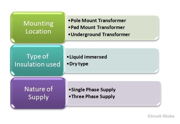
The various types of the distribution transformer are categorized on the following basis and is shown in the figure below
- Mounting location
- Type of insulation
- Nature of supply
 The distribution transformer less than 33 KV is used in industries and 440, 220 V is used for the domestic purpose. It is smaller in size, easy to install and has low magnetic losses and is not always loaded fully. As it does not work for constant load through out 24 hours as in the daytime its load is at its peak, and during the night hours it is very lightly loaded thus the efficiency depends on load cycle and is calculated as All Day Efficiency. The distribution transformers are designed for maximum efficiency of 60 to 70%
Uses of Distribution Transformer
- Used in pumping stations where the voltage level is below 33 KV
- Power supply for the overhead wires railways electrified with AC
- In urban areas, many houses are fed with single phase distribution transformer and in rural areas, it may be possible that one house requires one single transformer depending upon the loads.
- Multiple distribution transformers are used for Industrial and commercial areas.
- Used in wind farms where the electrical energy is generated by the windmills. There it is used as a power collector to connect the substations which are away from the wind energy generation system.
Instrument Transformer
- They are generally known as an isolation transformer. Instrument transformer is an electrical device used to transform current as well as voltage level. The most common use of instrument transformer is to safely isolate the secondary winding when the primary has high voltage and high current supply so that the measuring instrument, energy meters or relays which are connected to the secondary side of the transformer will not get damaged.The instrument transformer is further divided into two types
- Current Transformer (CT)
- Potential Transformer (PT)
The current and potential transformer is explained below in detail
Current Transformer
- The current transformer is used for measuring and also for the protection. When the current in the circuit is high to apply directly to the measuring instrument, the current transformer is used to transform the high current into the desired value of the current required in the circuit.
- The primary winding of the current transformer is connected in series to the main supply and the various measuring instruments like ammeter, voltmeter, wattmeter or protective relay coil.They have accurate, current ratio and phase relation to enable the meter accurately on the secondary side.The term ratio has a great significance in CT.
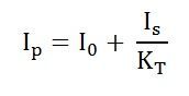
- For example, if its ratio is 2000:5, it means a CT has an output of 5 Ampere when the input current is 2000 amp on the primary side. The accuracy of the Current Transformer depends upon many factors like Burden, load, temperature, phase change, rating, saturation, etc.In the current transformer, the total primary current is the vector sum of the excitation current and the current equal to the reversal of secondary current multiplied by turn ratio.
Potential Transformer
The potential transformer is also called as the voltage transformer. The primary winding is connected across the High voltage line whose voltage is to be measured, and all the measuring instruments and meters are connected to the secondary side of the transformer. The main function of the Potential transformer is to step down the voltage level to a safe limit or value. The primary winding of the potential transformer is earthed or grounded as a safety point.
For example the voltage ratio primary to secondary is given as 500:120, it means the output voltage is of 120 V when the 500 V is applied to the primary. The different types of potential transformer are shown below in the figure
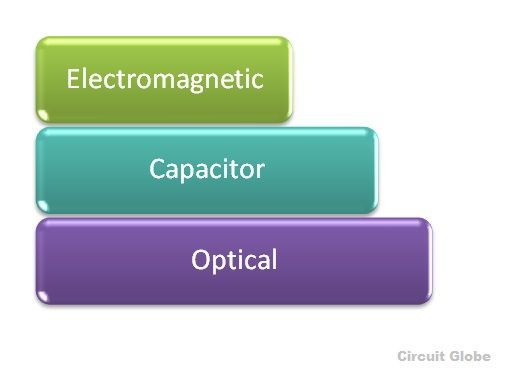
- Electromagnetic (it is a wire wound transformer)
- Capacitor (capacitor voltage transformer CVT uses capacitor voltage divider)
- Optical (works on the electrical property if optical materials)
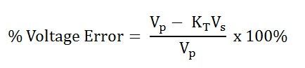
The percentage voltage error is given by the equation shown below
Single Phase Transformer
A single phase Transformer is a static device, works on the principle of Faraday’s law of mutual Induction. At a constant level of frequency and variation of voltage level, the transformer transfers AC power from one circuit to the other circuit. There are two types of windings in the transformer.The winding to which AC supply is given is termed as Primary winding and in the secondary winding, the load is connected.
Three Phase Transformer
If the three single phase transformer is taken and connected together with their all the three primary winding connected to each other as one and all the three secondary windings to each other, forming as one secondary winding, the transformer is said to behave as three phase transformer, that means a bank of three single phase transformer connected together which acts as a three-phase transformer.
Three phase supply is mainly used for electric power generation, transmission and distribution for industrial purpose. It is less costly to assemble three single phase transformer to form three-phase transformer than to purchase one single three-phase transformer. The three-phase transformer connection can be done by Star (Wye) and Delta (Mesh) type.
The connection of primary and secondary winding can be done by various combinations shown below
Primary Winding
|
Secondary Winding
|
|---|---|
Star (Wye)
|
Star
|
Delta (mesh)
|
Delta
|
Star
|
Delta
|
Delta
|
Star
|
The combination of primary winding and the secondary winding is done as star-star, delta-delta, star-delta and delta-star.
Methods of Cooling of Transformer
Based on the coolant used the cooling methods can be classified into:
- Air cooling
- Oil and Air cooling
- Oil and Water cooling
1. Air cooling (Dry type transformers)
- Air Natural(AN)
- Air Blast (AB)
2. Oil cooling (Oil immersed transformers)
- Oil Natural Air Natural (ONAN)
- Oil Natural Air Forced (ONAF)
- Oil Forced Air Natural (OFAN)
- Oil Forced Air Forced (OFAF)
3. Oil and Water cooling (For capacity more than 30MVA)
- Oil Natural Water Forced (ONWF)
- Oil Forced Water Forced (OFWF)
1. Air Cooling (Dry Type Transformers)
In this method, the heat generated is conducted across the core and windings and is dissipated from the outer surface of the core and windings to the surrounding air.

Air Natural (AN)
This method uses the ambient air as the cooling medium. The natural circulation of the air is used for dissipation of heat generated by natural convection. The core and the windings are protected from mechanical damage by providing a metal enclosure. This method is suitable for transformers of rating up to 1.5MVA. This method is adopted in the places where fire is a great hazard.

Air Blast (AB)
In this method, the transformer is cooled by circulating continuous blast of cool air through the core and the windings. For this external fans are used. The air supply must be filtered to prevent accumulation of dust particles in the ventilating ducts.
2. Oil cooling (Oil immersed transformers)
In this method, heat is transferred to the oil surrounding the core and windings and it is conducted to the walls of the transformer tank. Finally, the heat is transferred to the surrounding air by radiation and convection.
Oil coolant has two distinct advantages over the air coolants.
- It provides better conduction than the air
- High coefficient of conduction which results in the natural circulation of the oil.

Oil Natural Air natural (ONAN)
The transformer is immersed in oil and the heat generated in the cores and the windings is passed on to oil by conduction. Oil in contact with the surface of windings and core gets heated up and moves towards the top and is replaced by the cool oil from the bottom. The heated oil transfers its heat to the transformer tank through convection and which in turn transfers the heat to the surrounding air by convection and radiation.
This method can be used for the transformers having the ratings up to 30MVA. The rate of heat dissipation can be increased by providing fins, tubes and radiator tanks. Here the oil takes the heat from inside the transformer and the surrounding air takes away the heat from the tank. Hence it can also be called as Oil Natural Air natural (ONAN) method.

Oil Natural Air Forced (ONAF)
In this method, the heated oil transfers its heat to the transformer tank. The tank is made hollow, and the air is blown to cool the transformer. This increases the cooling of transformer tank to five to six time its natural means. Normally this method is adopted by externally connecting elliptical tubes or radiator separated from the transformer tank and cooling it by air blast produced by fans. These fans are provided with automatic switching. When the temperature goes beyond the predetermined value, the fans will be automatically switched on.
Oil Forced Air Natural (OFAN)
In this method, copper cooling coils are mounted above the transformer core. The copper coils will be fully immersed in the oil. Along with the oil natural cooling, the heat from the core passes to the copper coils, and the circulating water inside the copper coil takes away the heat. The disadvantage of this method is that since water enters inside the transformer any kind of leakage will contaminate the transformer oil.

Oil Forced Air Forced (OFAF)
In this method, the oil is cooled in the cooling plant using air blast produced by the fans. These fans need not be used all the time. During low loads, fans are turned off. Hence the system will be similar to that of Oil Natural Air natural (ONAN). At higher loads, the pumps and fans are switched on, and the system changes to Oil Forced Air Forced (OFAF). Automated switching methods are used for this conversion such that as soon as the temperature reaches a certain level, the fans are automatically switched on by the sensing elements. This method increases the system efficiency. This is a flexible method of cooling in which up to 50% of rating ONAN can be used, and OFAF can be used for higher loads. This method is used in transformers having ratings above 30MVA.
3. Oil and Water Cooling
In this method along with oil cooling, water is circulated through copper tubes which enhance the cooling of transformer. This method is normally adopted in transformers with capacities in the order of several MVA.

Oil Forced Water Forced (OFWF)
In this method, copper cooling coils are mounted above the transformer core. The copper coils will be fully immersed in the oil. Along with the oil natural cooling the heat from the core passes to the copper coils and the circulating water inside the copper coil takes away the heat. The disadvantage in this method is that since water enters inside the transformer any kind of leakage will contaminate the transformer oil. Since heat passes three times as rapidly from copper cooling tube to water as from oil to copper tubes, the tubes are provided with fans to increase the conduction of heat from oil to tubes. The water inlet and outlet pipes are lagged in order to prevent the moisture in the ambient air fro condensing on the pipes and getting into the oil.


I cannot thank Mr Benjamin service enough and letting people know how grateful I am for all the assistance that you and your team staff have provided and I look forward to recommending friends and family should they need financial advice or assistance @ 1,9% Rate for Business Loan .Via Contact : . 247officedept@gmail.com. WhatsApp...+ 19893943740. Keep up the great work.
ReplyDeleteThanks, Busarakham.