Rotor
DefinitionThe rotor is a moving component of an electromagnetic system in the electric motor, electric generator, or alternator. Its rotation is due to the interaction between the windings and magnetic fields which produces a torque around the rotor's axis.
Types of rotor
Induction (asynchronous) motors, generators and alternators (synchronous) have an electromagnetic system consisting of a stator and rotor. There are two designs for the rotor in an induction motor: squirrel cage and wound. In generators and alternators, the rotor designs are salient pole or cylindrical.Induction (asynchronous) motors, generators and alternators (synchronous) have an electromagnetic system consisting of a stator and rotor. There are two designs for the rotor in an induction motor: squirrel cage and wound. In generators and alternators, the rotor designs are salient pole or cylindrical.
Squirrel-cage rotor

Wound rotor


The rotor is a cylindrical core made of steel lamination with slots to hold the wires for its 3-phase windings which are evenly spaced at 120 electrical degrees apart and connected in a 'Y' configuration.The rotor winding terminals are brought out and attached to the three slips rings with brushes, on the shaft of the rotor.Brushes on the slip rings allow for external three-phase resistors to be connected in series to the rotor windings for providing speed control.The external resistances become a part of the rotor circuit to produce a large torque when starting the motor. As the motor speeds up, the resistances can be reduced to zero.
Salient pole rotor


Cylindrical rotor
The cylindrical shaped rotor is made of a solid steel shaft with slots running along the outside length of the cylinder for holding the field windings of the rotor which are laminated copper bars inserted into the slots and is secured by wedges. The slots are insulated from the windings and are held at the end of the rotor by slip rings. An external direct current (DC) source is connected to the concentrically mounted slip rings with brushes running along the rings. The brushes make electrical contact with the rotating slip rings. DC current is also supplied through brushless excitation from a rectifier mounted on the machine shaft that converts alternating current to direct current.
Working principle
In a three-phase induction machine, alternating current supplied to the stator windings energizes it to create a rotating magnetic flux. The flux generates a magnetic field in the air gap between the stator and the rotor and induces a voltage which produces current through the rotor bars. The rotor circuit is shorted and current flows in the rotor conductors.The action of the rotating flux and the current produces a force that generates a torque to start the motor.
An alternator rotor is made up of a wire coil enveloped around an iron core.The magnetic component of the rotor is made from steel laminations to aid stamping conductor slots to specific shapes and sizes. As currents travel through the wire coil a magnetic field is created around the core, which is referred to as field current. The field current strength controls the power level of the magnetic field. Direct current (DC) drives the field current in one direction, and is delivered to the wire coil by a set of brushes and slip rings. Like any magnet, the magnetic field produced has a north and a south pole. The normal clockwise direction of the motor that the rotor is powering can be manipulated by using the magnets and magnetic fields installed in the design of the rotor, allowing the motor to run in reverse or counterclockwise.
Characteristics
- Squirrel cage rotor
- This rotor rotates at a speed less than the stator rotating magnetic field or synchronous speed.
- Rotor slip provides necessary induction of rotor currents for motor torque, which is in proportion to slip.
- When rotor speed increases, the slip decreases.
- Increasing the slip increases induced motor current, which in turn increases rotor current, resulting in a higher torque for increase load demands.
- Wound rotor
- This rotor operates at constant speed and has lower starting current
- External resistance added to rotor circuit, increases starting torque
- Motor running efficiency improves as external resistance is reduced when motor speed up.
- Higher torque and speed control
- Salient pole rotor
- This rotor operates at a speed below 1500 rpm (revolutions per minute) and 40% of its rated torque without excitation
- It has a large diameter and short axial length
- Air gap is non uniform
- Rotor has low mechanical strength
- Cylindrical rotor
- The rotor operates at speed between 1500-3000 rpm
- It has strong mechanical strength
- Air gap is uniform
- Its diameter is small and has a large axial length and requires a higher torque than salient pole rotor
Rotor bar voltage
The rotating magnetic field induces a voltage in the rotor bars as it passes over them. This equation applies to induced voltage in the rotor barswhere:- = induced voltage
- = magnetic field
- =conductor length
- =synchronous speed
- = conductor speed
Torque in rotor
A torque is produced by the force produced through the interactions of the magnetic field and current as expressed by the given: Ibidwhere:- =force
- =torque
- =radius of rotor rings
- =rotor bar
Induction motor slip
A stator magnetic field rotates at synchronous speed, Ibidwhere:- = frequency
- = number of poles
If = rotor speed, the slip, S for an induction motor is expressed as:mechanical speed of rotor, in terms of slip and synchronous speed:Relative speed of slip:Frequency of induced voltages and currents
- what is slip?
An AC (Alternating Current) induction motor consists of a stator and a rotor and the interaction of the currents flowing in the rotor bars and the rotating magnetic field in the stator generates the torque that turns the motor. In normal operation with a load the rotor speed always lags the magnetic field's speed allowing the rotor bars to cut magnetic lines of force and produce a useful torque.
The difference between the synchronous speed of the magnetic field, and the shaft rotating speed is slip - measured in RPM or frequency.- Slip increase with increasing load - providing greate0r torque.
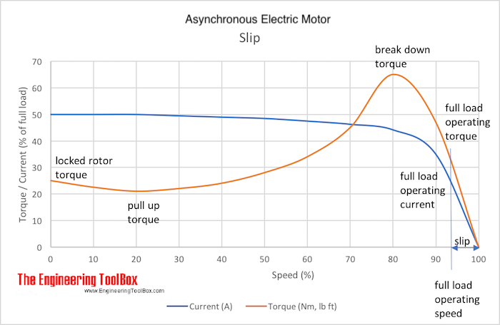
- It is common to express the slip as the ratio between the shaft rotation speed and the synchronous magnetic field speed.S = (ns - na) 100% / ns (1)whereS = slipns = synchronous speed of magnetic field (rev/min, rpm)na = shaft rotating speed (rev/min, rpm)When the rotor is not turning the slip is 100 %.Full-load slip varies from less than 1 % in high hp motors to more than 5-6 % in minor hp motors.
Motor Size
(hp)0.5 5 15 50 250 Typical Slip
(%)5 3 2.5 1.7 0.8 Number of poles, frequencies and synchronous induction motor speed
No. of magnetic poles Frequency (Hz) 50 60 2 3000 3600 4 1500 1800 6 1000 1200 8 750 900 10 600 720 12 500 600 16 375 450 20 300 360


No comments:
Post a Comment